Sunday, January 20, 2013

STL view and repair tool

STL (STereoLithography) is a file format native to the stereolithography CAD software created by 3D SystemsSTL files describe only the surface geometry of a three dimensional object without any representation of color, texture or other common CAD model attributes. All the things you get from www.thingiverse.com are in STL format. I found netfabb Studio Basic when I was looking for a free STL viewer. It turned out that I could not only view STL files, but also repair, measure and cut STL files.

Viewing STL files

After opening the STL file in netfabb, you can zoom in and out, using the mouse scroll wheel. You can turn the object clicking the right mouse button and dragging the mouse.

Automatic STL repair

Exclamation mark in netfabb
I have used the repair function quite a few times. When you load a STL file for viewing, netfabb notifies you when a repair action is necessary. You get a warning when you slice such a file with Slic3r in Pronterface. netfabb notifies you by showing an exclamation mark in the lower right corner. For example the whistle: http://www.thingiverse.com/thing:1046. My first print wasn't even hollow! The automatic repair function fixed that for me. You can fix a STL file using netfabb by following these steps:
  • Open the STL using netfabb;
  • Notice the exclamation mark in the right lower right corner telling you the STL needs to b repaired;
  • On the main menu click 'Extras/Repair part';
  • On the main menu Click 'Repair/Automatic repair';
  • In the Automatic repair dialog Click 'Execute';
  • In the lower right corner click the 'Apply repair' button;
  • Click 'Yes' to remove the old part;
  • On the main menu click 'Part/Export part/as STL' to save the repaired STL file to disk.

Cut STL files
STL file cut on X axis
Netfabb allows you to cut a model in pieces and save each part as a separate STL file. This was convenient when I wanted to print the cap of a bottle in a different color than the bottle itself. The buttons and sliders in the lower right corner allow you to make a cut in the X, Y and/or Z axis. The part in the image is the Twisted Bottle available in thingiverse. Use the slider to select a point where to cut. Then press the 'Execute cut' and 'Cut' button. After this you can select the cap and the bottle individually and save them as a separate STL file by clicking 'Part/Export part/as STL' from the menu.


Measure
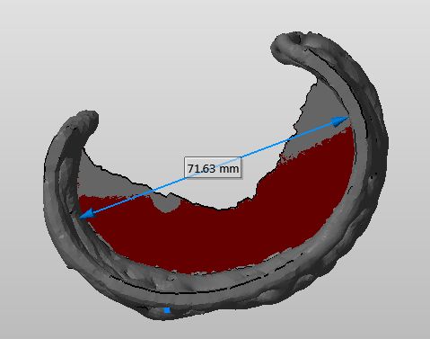
Another feature that I find convenient, is the measure tool in netfabb. It allows you to measure an object in the STL file. I have used it to scale a bangle down to fit the wrist of my nine year old daughter. To make a measurement click 'Extras/New Measuring' from the menu. Now click on two points in the model to create a line showing the distance. Use the mouse as described to rotate and zoom the model while placing the measure points.

Thursday, January 17, 2013

Slic3r 0.7.1 versus 0.9.8

The precompiled Pronterface I am using comes with Slic3r version 0.7.1. The current version  of Slic3r as I write this text is 0.9.8. Slic3r is the tool you need to convert a digital 3D model into printing instructions for your 3D printer. It cuts the model into horizontal slices (layers), generates toolpaths to fill them and calculates the amount of material to be extruded.  An  issue with the printed result made me decide to try the new version. 


Part left Slic3r 0.7.1, part right Slic3r 0.9.8
The left part in the picture is sliced with Slic3r 0.7.1 and the right part is sliced with Slic3r 0.9.8. The difference is that the left part has hollow walls. The hollow walls made me decide to try the new version. Note that the hollow walls are not part of the design! You can check out the design yourself at: http://www.thingiverse.com/thing:20830. As you can see on the right, this issue is fixed in the latest version. Another improvement, Coen pointed me at, is that the printed surface is smoother.

Part left Slic3r 0.7.1, part right Slic3r 0.9.8

When you look closely at the left part in the image above, you notice a line from top to bottom. It marks the place where the printer head made a step to the next Z-level (height). The part on the right does not have this line.