Monday, December 31, 2012

Prusa Mendel 3D-printer up and running!

First print
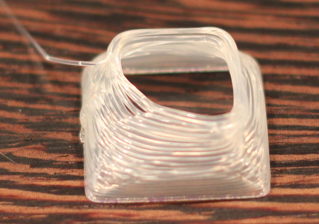
Four days ago I had my Prusa Mendel (iteration 2) 3D-printer up and running. First thing I printed was a small glass to celebrate it. I downloaded the glass from thingiverse. I created an account on thingiverse on which you can check out the things I have created up to now.

My 3D-printer and some objects I have printed with it


It is a tradition to print a glass as a first object

Setting up the firmware
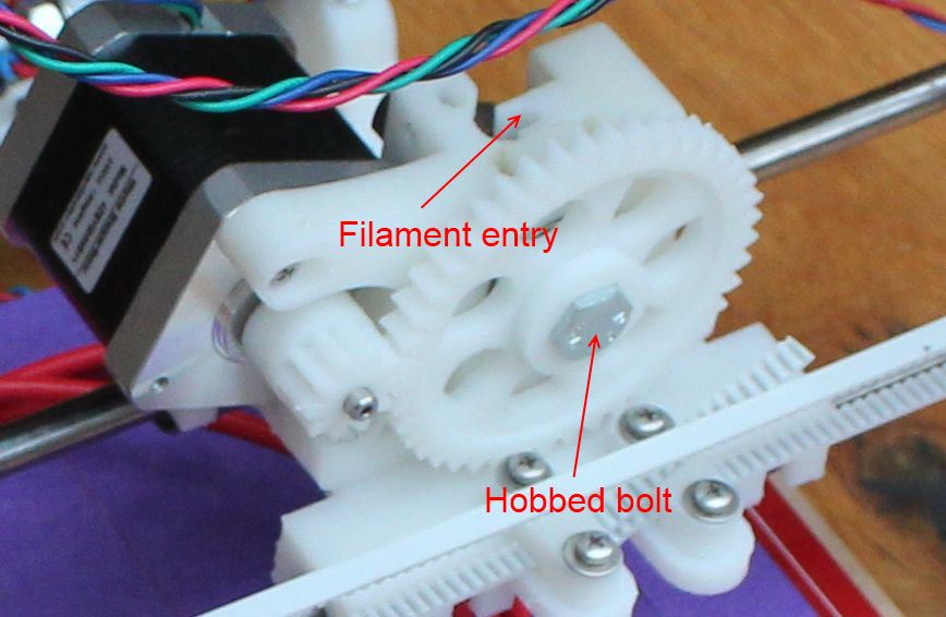
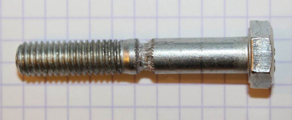
First thing I had to set in the firmware was the extruder value for my hobbed bolt. I bought a hobbed bolt/bar from Arcol (hyena 1.1) as well as one from RepRap-FabSee my entry from October 20th on how to calibrate the extruder.

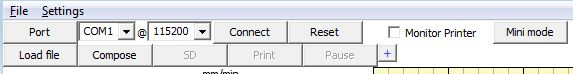
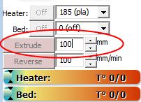
After setting the correct value for the extruder, I had to make sure that the X, Y, Z and Extruder motors would move in the correct direction. This has to be set in the firmware, just like the extruder value. Pronterface enables you to move the motors manually. See the controls in the image below.


Pronterface interface for manual control

The buttons should give the results below. Check the image of the printer above for what is meant by 'front'.

[-x]: move the extruder to the left (until the end stop).
[+x]: move the extruder to the right.

[-y]: move the print bed to the rear (until the end stop).
[+y]: move the print bed to the front.

[+z]: extruder up.
[-z]: extruder down (until the end stop).

[Extrude]: move the filament into the extruder.
[Reverse]: retract the filament out of the extruder.

I had to modify some values in the file Configuration.h to get the motors spinning in the right direction.

//-------------------------
// Inverting axis direction
//-------------------------
const bool INVERT_X_DIR = true;
const bool INVERT_Y_DIR = true;
const bool INVERT_Z_DIR = true;
const bool INVERT_E_DIR = true;

Getting Pronterface to print
The great moment: load a model and hit the Print button! Then nothing happens... After some research I found the problem: I had used the Slic3r 0.9.7 wizard to generate a config.ini file. The Slic3r wizard had set the bed temperature to 5 degrees. The issue with this is that I do not have a heated bed nor the thermistor in place. After hitting the Print button Pronterface will heat up the print head and the heated bed up to the configured temperature. With no thermistor in place, the microcontroller will always read 0 for the temperature. After modifying the config.ini file, Pronterface was printing fine!

CAD software for kids
Because my kids (9 and 10 years old) are very interested in the 3D-printer, I was looking for CAD-software that they could use. I found tinkercad and really love it. It is online software, so you don't have to install anything. They have free online courses. By using Chrome as a browser and its translation functionality, the kids could easily follow along.

Thursday, December 20, 2012

Building my own Prusa Mendel

Coen has his Prusa Mendel up and running and has printed the Prusa Mendel plastic parts for me. The photo shows the current state of the build. I am in the process of gathering all the components.

My own Prusa Mendel


Saturday, October 20, 2012

Calibrating the Prusa Mendel and get it to print

I wanted to build a mini sumo, and now I am calibrating a Prusa Mendel 3D printer!


Software installation

The first step is to install the software needed:

Virtual COM port

The 3D printer is connected to the PC using an USB cable. After installing the driver you will get an extra (virtual) COM port through which the printer can be accessed.

Pronterface

Pronterface
Pronterface is the user interface software for controlling the 3D printer. I prefer the precompiled version because it does not require installation of Python.

Sprinter

Sprinter is the firmware for the 3D printer. The software runs on the 3D printer itself. The 3D printer lend to me has the Sanguinololu 1.3a board. At the time of this writing, the software is based on Arduino 0023. So you need to install that specific version if you need to compile this software. Check the Sprinter page if this is still true.

Arduino

Arduino 0023 is used to compile Sprinter.


ABS or PLA?

ABS requires a functioning heat bed while PLA can be printed on a heat bed at room temperature. Because I do not have a power supply that is able to provide the amount of current needed by the heat bed PCB, PLA is the only option for me. PLA is made from corn and melts around 185 degrees Celsius  ABS is an oil product and is used in 3D printer at a temperature of 220 degrees Celsius.


A new hobbed bolt

When I bring nozzle of the printer to temperature and extrude some PLA, the same thing happens again and again: after some time, the filament stops while the extrusion motor and bolt are still spinning. 


The extruder
Original hobbed bolt

New hobbed bolt made by Coen
The filament is clamped between the notch in the hobbed bolt and a ball-bearing. The filament is extruded by turning the hobbed bolt. It turns out that the teeth of the hobbed bolt are somewhat blunt. Coen, a handy friend makes a new hobbed bolt with some more impressive teeth!

Extruder calibration


After installation of the virtual COM port driver and Pronterface, you can use Pronterface to connect to the printer. Select the correct COM port and hit the Connect button.


Use the extrude button to calibrate the extruder. First remove the hot end from extruder so that the filament can run freely without any obstruction. Mark the filament and hit the extrude button after filling in 100 mm.


Now measure the amount of filament run though the extruder. When it is not exactly 100 mm (+/- 1 mm), you must make a correction in the Sprinter firmware. Open the Sprinter file Configuration.h and search for the lines:


//// Calibration variables
// X, Y, Z, E steps per unit - Metric Prusa Mendel with Wade extruder:
#define _AXIS_STEP_PER_UNIT {80, 80, 3200/1.25, 700}

700 is the value you have to update. With my hobbed bolt a value of 633.6 gave the correct amount of throughput. Compile and upload to the printer. First I got next error message:
avrdude: stk500_getsync(): not in sync: resp=0x00 
avrdude: stk500_disable(): protocol error, expect=0x14, resp=0x51 

I fixed that by lowering the upload speed. To lower the upload speed, open the file C:\Program Files\arduino-0023\hardware\Sanguino\boards.txt and change the line atmega644.upload.speed=57600 to atmega644.upload.speed=38400.


A flat surface to print on

After I got the extrusion speed correct it turned out that the heated bed PCB was not flat. It was somewhat bathtub shaped. With a height difference of three mm. That was fixed with a piece of glass on top of the heated bed. Now try to print a 0.5mm_single_wall_calibration_piece. First result:


Printing directly on the glass surface
The PLA does not stick to the glass surface. The image above speaks for itself.


Print result after adding blue tape to the glass surface
Second try after applying tape the the glass surface. Now it seems that the layers do not stick enough to the layers below.


Print result after blowing air while printing
For the third try, we blew some air on the piece, while printing. The result was that the filament got stuck somewhere in the hot end.


A different head

Every time I try to print something, the filament gets stuck. First the hobbed bolt was the suspect, but that has been fixed. Next suspect is the hot end. As an experiment the hobbed bolt and gears are removed so that the filament can be extruded by hand. At the start it is easy to push the filament down, but after a short while, the filament blocks. Than it is not possible the push the filament down. The friend who also created the hobbed bolt read positive things about the J Head. He ordered one and put it in place. The image below shows the result after printing the single wall calibration piece.


Woohoo: good results with J Head!
Now that the calibration piece is successfully printed we can finally try to print the pencil hinge. That's what started this 3D printing journey.


The pencil hinge that started the 3D printer journey
Again success. Now that we made this 3D print journey to a success and learned a lot about 3D printing, Coen and I want our own 3D printer. Time for printer reproduction!


Printing parts for a 'child' printer


The first child printer (Coen's) begins to take shape

Friday, October 19, 2012

Materializing the pencil hinge

Now that I have my pencil hinge design in the computer; it would be awesome if I could hit a 'materialize' button and have it in my hands a few moments later! Just like in a SF movie. But wait: with the current 3D printing technology, that is no longer science fiction! I was curious how this part would look like when printed with a hobby 3D printer. I found a very friendly person how had build a Prusa Mendel. He build it a year ago but never got it working correctly. After some unsuccessful attempts to get it working he put it the closet. There was a problem with the alignment and the printer head. He was willing to lend it to me. The deal was: if I would calibrate it and get it up and running I could print my pencil hinge part for free. How awesome is that? Only the experience of getting my hands dirty with this printer is great. In the past I already had considered building one but new found a good use for it.

Prusa Mendel 3D printer

Thursday, October 18, 2012

Mini Sumo Pencil Hinge

--> I am in the process of building my own incarnation of the Number Two autonomous mini sumo robot. For me as a professional technical software engineer with a background in electronics, the mechanical parts are the hardest. Especially the part in which the pencils will hinge. I do not have the tool to create it from a massive piece of aluminium or the like. To get my head around this part and make it visible for myself and others, I decided to make a 3D drawing first. While searching for a 3D drawing tool, I came across OpenSCAD. It is advertised as 'The Programmers Solid 3D CAD Modeller'.


OpenSCAD
The tool is ideal for me as a software developer. For me it is far more easy to type something like 'cube([98, 15, 14])' to create a cube of 98 by 15 by 14 mm, than dragging things around on the screen and trying the get the size correct. The left part of the screen is for editing the text and on the right you can see the resulting image.


First try

The code to create the image above:
module PencilHinge()
{
  hole_width = 8.1;
  hole_count = 8;
  total_width = 98;
  projection_count = 9;
  projection_width = (total_width-(hole_count*hole_width)) / projection_count;

  difference()
  {
    union()
    {
      cube([98, 15, 14], center = true);
    }
    union()
    {
      for ( i = [0:7] )
      {
        translate(v=[i *(hole_width+projection_width)-(total_width/2)+hole_width,0,4])
        {
          cube([8.1, 16, 16], center = true);
        }
      }
      translate(v=[0, 0, 1])
      {
        rotate(a = [0, 90, 0])
        {
          cylinder(h = 100, r=1, center = true);
        }
      }
    }
  }
}

PencilHinge();

After playing one hour with it I came up with the design above. When you look at the full size image you can see that the holes are not round, but consist of just seven flat surfaces.


Second iteration

A second night working on it I found out that you can set the number of surfaces used to make the cylinder holes: I had to add $fn=36 to the creating of the cylinder. Where 36 is the number of surfaces: cylinder(h = 100, r=2, center = true, $fn=36); I added eight holes in the bottom plate to be able to mount it to the robot frame. The holes for the nuts were, easy now that I now how to set the number of surfaces of the cylinder. I just needed six surfaces for that.

The code for the image above:

module PencilHinge()
{
  // Sizes in mm
  round_r = 3;
  pad = 0.1;
  mounting_hole_radius = 1.5;
  mounting_nut_r = 6.3 / 2;
  mounting_nut_h = 2.5;
  mounting_nut_facets = 6;
  hole_count = 8;
  projection_count = hole_count + 1;
  hole_width = 8.1;
  box_l = 98;
  box_w =15;
  box_h = 14;
  projection_width = (box_l-(hole_count*hole_width)) / projection_count;

  difference()
  {
    union()
    {
      // The main part
      cube([box_l, box_w, box_h], center = true);
    }
    union()
    {
      for (i = [0:7])
      {
        translate(v=[i *(hole_width+projection_width)-(box_l/2)+hole_width,0,4])
        {
          // Holes to hold the pencils
          cube([hole_width, box_w+pad, box_h], center = true);
          // Mounting hole
          cylinder(h = box_l, r=mounting_hole_radius, center = true, $fn=36);
          // Nut hole
          cylinder(h = (mounting_nut_h*2)+box_h, r=mounting_nut_r, center = true, $fn=mounting_nut_facets);
        }
      }
      // The axle
      translate(v=[0, 0, 3])
      {
        rotate(a = [0, 90, 0])
        {
          cylinder(h = box_l+pad, r=1, center = true, $fn=36);
        }
      }
    }
  }
}

PencilHinge();


Final design


It took a third night to come to the final design shown in the image above, with nice rounded corners. I used the cube fillet module for that. I only had the replace cube([box_l, box_w, box_h], center = true); by cube_fillet([box_l, box_w, box_h], vertical=[0,0,0,0], top=[round_r,0,round_r,0], center=true); Note that the cube filet code to get the rounded corners is bigger in size than the pencil hinge code.

Mechanical build of the mini sumo

Some photos of the mechanical and electrical build.


I have cut a piece of the plastic for the robot body. 98 mm wide and 85 mm long. Two pieces of aluminum are connected to the body. The front piece will be the base for the thing that will hold the pencils. The second piece is used to fix and align the motor on. Tie-wraps are used to keep the motors in place.


As a third 'wheel' I use a Tamiya 70144 Ball Caster Kit.


I use a piece of prototyping PCB to solder the components. Because I'm only going to make one robot, there is no need to design and etch a PCB. The two black vertical strips will hold the STM32F4 Discovery board. The red board is the motor driver.


The result up till now, complete with the STM32F4 Discovery board in place.

Wednesday, October 17, 2012

Selecting a C/C++ toolchain for the STM32F4DISCOVERY

Selecting a toolchain for the STM32F4DISCOVERY board of  my new to build mini sumo. The board contains a STM32F407VGT6 microcontroller featuring 32-bit ARM Cortex-M4F core, 1 MB Flash, 192 KB RAM in an LQFP100 package. With this tool chain I need to be able to compile, write the code to the microcontrollers flash and debug. I prefer C++ over C, because C++ allows object oriented constructs more easily than C. There are commercial vendors (like Keil and IAR) that have an evaluation version that has a code limit of 32 kbyte. Such a ‘crippled’ version is not an option for me. The full version is also not an option because it is a hobby project and I don’t want to spend too much money on it. After some research I found a free toolchain called ‘CooCox. It is a complete toolchain, you have to add a compiler however. I used YAGARTO for that. CooCox doesn’t support C++ natively but I found two threads in the forum on how to use it with C++ (http://www.coocox.org/forum/topic.php?id=730 and http://www.coocox.org/forum/topic.php?id=873). My object oriented version of the ‘Hello LED’ program works like a charm!

Tuesday, October 16, 2012

Parts for a new mini sumo robot

Last September 2012 I started gathering parts for a new to build mini sumo robot. With my previous mini sumo called QuanI became Benelux mini sumo champion several times. I build that robot in 2005. Last time I participated in the competition in 2009, I became second. Since that moment, the robot has not left the closet for a new match. Now I have plans for a new robot inspired by a mini sumo called Number Two. A mini sumo robot is an autonomous robot not weighing more than 500 grams and limited in size 10 by 10 cm during start.
Parts for my new to build mini sumo
The parts in the picture:
Although I am aware that technology is ever moving forward in a seemingly increasing speed it is still amazing if you compare the microcontrollers available then and now for my new robot.


2005 mini sumo 2012 mini sumo
Processor ATmega32 (8-bits) STM32F407VGT6 (ARM 32-bit Cortex™-M4 CPU)
Clock speed (MHz) 16 168
Flash 32 KB 1 MB
SRAM 2 KB 192 KB
Timers 2x 8-bit, 1x 16-bit 12x 16-bit, 2x 32-bit
Peripherals 10-bit ADC, I2C, USART, SPI, RTC. 3x I2C, 4x USART, 2x UART, 3x SPI, 2x CAN, SDIO, USB, Ethernet, Camera interface, True random generator, CRC calculcation unit, RTC.